
Industrial Computed Tomography (CT) for Additive Manufacturing Inspection and Quality Assurance.
- Nov 28, 2017
- 2 min read
With the rapid growth of additive manufacturing, new challenges relative to inspection of internal details of an AM part have become apparent. Complex passageways and volumes can be built directly into a part, but what assurance does the manufacturer have that these hidden regions turned out as planned? In this story, we present how industrial CT is useful in determining if residual material is left in passages, or is trapped in stagnation areas, and have escaped the cleaning process.
Figure 1 shows the CAD model of a part that is a candidate for additive manufacturing. Note that making the internal cavities would take multiple processes to fabricate with traditional machining and joining technology. Verification of the cavities’ condition is a challenge regardless of manufacturing method here.
Fig 1: 3D CAD rendering on the left prior to manufacture. Aluminum 3D printed aluminum block on the right.

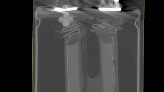
Industrial CT Visualization of Additive Manufactured Part
This image (Figure 2) shows the results of a CT scan of the actual AM product, fabricated per the SL

A from the CAD model. It was manufactured via Direct Metal Printing, using an aluminum alloy powder bed and a laser. This particular CT image shows the actual part virtually sliced. The display is set with the material displayed as partially transparent, such that multiple cavities can be visualized.
This image (Fig 3) shows the CT scan results highlighting a low density deposit within the part. It was detected and highlighted in red using Volume Graphics post-processing. In the far right image below the detail of the low density material, filling much of the “star” cavity that was part of the original design. Using VG post-processing the volume of material in the un-fused trapped powder can also be quantified. Upon consultation with the manufacturing company, it was concluded that the post-fabrication purge of that cavity was inadequate, and would have to be modified.
Figure 3: CT scan of the part, with trapped powder highlighted in red. Zoomed in to show detail in the far right image.


Comments