Additive Manufacturing Infill Inspection - Comparison Solid vs Infill
How solid is “solid” in additive manufacturing?
One of the benefits of additive manufacturing is the ability to adjust the fill of an otherwise solid part. For example, AM parts are sometimes purposefully printed with a lattice internal structure rather than printed solid, when the structural integrity of the part is unlikely to be compromised in its application. Inserting lattice or infill structures to the interior of additively manufactured parts can significantly reduce the weight of a part. The cost for parts going to space can cost thousands of dollars per kilogram, so in those applications every gram counts. In the example below we demonstrate using a plastic part, however the same inspection principle applies all types of AM parts, including metals.
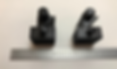
An example of this variation is illustrated by CT scanning two plastic AM parts of identical external geometry (below), but one being “hollow” (fractional infill) and the other “solid”.
These were printed by an AM company as example pieces for high volume production, and to illustrate that fill details could be modified depending on the structural requirements of the piece, mass requirements, or print cost (time and materials).
These two parts were non-destructively CT scanned to inspect the quality of the lattice infill as compared to the solid infill. The video below shows the external surface of these parts, in the position they were CT scanned. Note that externally they are very similar.
Industrial CT Scan Video - Exterior Imaging (Solid vs. Infill look identical from exterior)
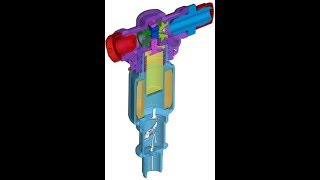
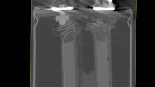
The video below shows the hollow unit is made up of a lattice fill (per design). The video also shows the other unit is solid, albeit has fill-path voids and imperfections. If the lattice design meets the structural requirements of the part, a customer may be quite pleased as it may save production time and costs on the mass produced part.
Industrial CT Scan Video - Interior Imaging: Solid (left side) vs. Infill (right side)
CT scanning illuminates the details of each part, allowing inspection of the print quality through the whole volume rather than just at a saw-cut section. Further, with post-processing the 3D data from the CT scan can be overlaid with the CAD design, showing deviations between design-intent and print-result. When evaluating the acceptability of an AM production part run, CT scanning is an excellent way to affirm the batch will meet the design intent.
With the results of CT scanning on all aspects of the fill, discontinuities, and design intent vs the actual part, the AM Customer can make an informed decision on the best part for their application.
Learn more about advanced analysis of additively manufactured parts, contact us for a free consultation or subscribe to our newsletter to for the latest in additively manufacturing inspection and quality control.